Pre-processing Algorithms
[edit] Geometry Preprocessing Algorithms
This section illustrates the computation algorithms related to building facade geometry (normal, tilt, azimuth, area), building height parameters (ridge and eves height), new volume calculator (based on simple polygonal data structure), center geocordinates of building geometry and sun & wind exposed/occluded facade geometry calculations. The underlying implementation support for algorithms is provided by CityDoctor project based on CityDoctor data structure. A CityDoctor data structure provides the vertex, edge, polygon tables for each building geometry. A building geometry of geometry type (SOLID/MULTISURFACE) consists of boundary surface polygons (linear rings) which are formed by vertices and edges. A polygon table stores the key-value pairs of Polygon ID and list of vertex IDs of linear ring while vertex table stores the key-value pairs Vertex ID and vertex coordinates.
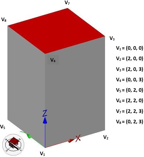
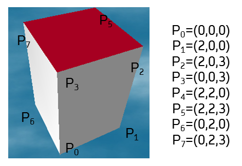
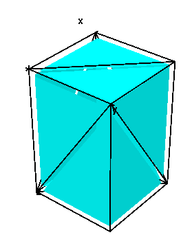
The demonstrated algorithm illustrations are tested with the help of basic cuboid geometry as shown (Volume-SimpleBldg.xml). The CityGML file contains a building model with a LoD2 solid geometry and boundary surfaces (Roof, Wall, Ground). The model is parsed and mapped to the internal CityDoctor data structure.
[edit] Surface Normal
The normal for a given boundary surface polygon say (linear ring: 1,2,3,4,1) as shown is calculated by considering the cross-product between the vectors defining a polygon plane (V2-V1) X (V4-V1) which results in unit components of that surface normal in x, y and z directions. The unit normal can be obtained from two different forms of implementations (first implementation is used in current revision and required vectors are calculated from supplied vertex table) -
1. double[] de.hft.stuttgart.featurehandler.PolygonHandler.getNormalOfSurface(Polygon polygon, HashMap<Integer, Vertex> vertextable) and
2. double[] de.hft.stuttgart.linearalgebra.Matrix.getVectorCrossMultiplication(double[] a, double[] b)
[edit] Surface Tilt
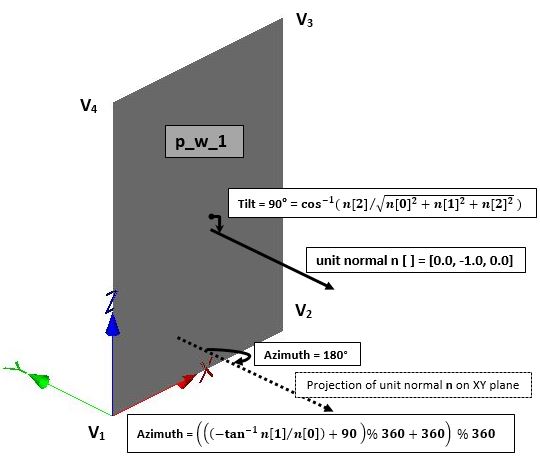
The tilt or inclination of wall surface polygon (1,2,3,4,1) as shown is equal to an angle between surface normal (n) and the plane containing the surface (XZ plane). The implemented method computes the cosine inverse between z-component and vector length of surface normal -
double de.hft.stuttgart.linearalgebra.Matrix.calcTilt(double[] n)
[edit] Surface Azimuth
The azimuth of surface polygon (1,2,3,4,1) as shown is equal to an angle between the projection of surface normal and north direction of geographic co-ordinate system. The implemented method computes the tangent inverse between the y-component and x-component of surface normal -
double de.hft.stuttgart.linearalgebra.Matrix.calcAzimuth(double[] n)
[edit] Surface Area
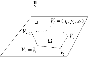
The area of 3D polygonal boundary surface geometry defined in certain plane as shown is related to the sum of the areas of 3D triangles (area of 3D triangle is equal to half the magnitude of cross-product between two adjacent edge vectors i.e. 0.5*|(V0-P) X (V1-P)|) formed by the two consecutive vertices say V0 & V1 of polygon and an arbitrary 3D point P (in general, point P = 0, 0, 0). These 3D triangles are projected on to the plane containing polygon and then, the sum of the areas of projected triangles gives the area of 3D polygonal geometry. A detailed procedure explaining the 3D planar polygon area computation algorithm is given at: http://geomalgorithms.com/a01-_area.html#2D%20Polygons
Therefore, the area of 3D polygon is given as:  where, n is the unit normal vector to the plane containing 3D polygonal surface as shown in figures.
However, in order to facilitate an efficient computation of 3D planar polygon area for ease of implementation and computation time reduction, the 3D polygon can be projected on to a 2D plane [Snyder & Barr, 1987]. Then, the area can be computed in 2D using efficient third summation formula for 2D polygons (explained in 2D polygons section of above link) and the 3D area is computed by using an area scaling factor. This method projects the 3D-embedded polygon onto an axis-aligned 2D subplane, by ignoring one of the three coordinates.
For instance, if (x,y,z) are the 3D coordinates for the standard xyz basis, then the projections that ignore x, y, and z are onto the yz, zx, and xy subplanes respectively. That is, the projections are given by: ![]() ,
, ![]() and
and ![]() . Then, the polygon's normal vector n is investigated, and the component with the greatest absolute value is chosen as the one to ignore.
. Then, the polygon's normal vector n is investigated, and the component with the greatest absolute value is chosen as the one to ignore.
Let ![]() be the projection that ignores the selected coordinate c = x, y, or z. Then, the ratio of areas for the projected polygon
be the projection that ignores the selected coordinate c = x, y, or z. Then, the ratio of areas for the projected polygon ![]() and original polygon
and original polygon ![]() with normal
with normal ![]() is given by:
is given by: 
This method of 3D area calculation is 6 times efficient than the classical formula mentioned above and uses n+5 multiplications, 2n+1 additions, 1 square root (when n is not a unit normal), plus a small overhead choosing the coordinate to ignore.
The implementation algorithm for surface area calculation considers an absolute value of normal, selects largest coordinate to ignore for projection, computes area of the 2D projection and scales 2D area to get the area before projection. The implemented method for surface area calculation requires the polygon, a normal vector of the polygon's plane and polygon vertices as input parameters -
double de.hft.stuttgart.featurehandler.PolygonHandler.getAreaOfPolygon(Polygon p, double[] N, HashMap<Integer, Vertex> vertices)
The surface area calculation is tested for the 3D polygonal boundary surface (1,2,3,4,1) as shown in above figure, where y coordinate of normal n is ignored for projection onto zx subplane. The area (= 12) of the 2D projection is computed using efficient third summation formula for 2D polygons and then this area is scaled by the ratio of areas for projected and original polygon to the 3D polygonal boundary surface area (= 6) before projection.
[edit] Building Height Parameters (Mean, Eaves and Ridge Height)
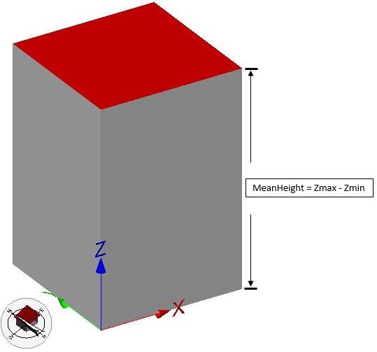
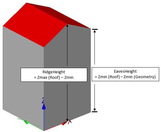
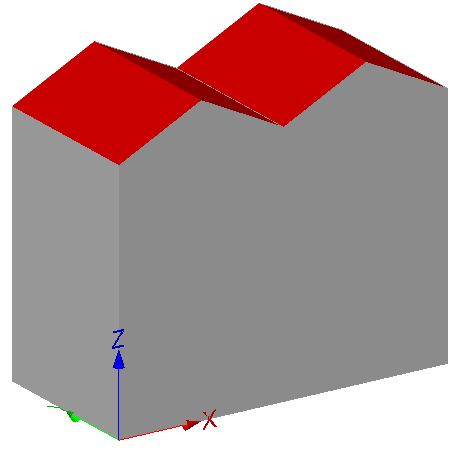
The building height calculation criteria varies depending upon the level of detail of geometry (LOD1/LOD2) as shown.
For LOD1 building model, a building height is equal to the mean height which is the difference between maximum and minimum z-value (minimum terrain height) of building geometry.
minTerrainHeight = GeometryHandler.getMinZ(geom)
meanHeight = GeometryHandler.getMaxZ(geom) - minTerrainHeight
While for LOD2 building model with prototype gable roof shape, a building height is categorized into two parameters: eaves and ridge height. Eaves height is the difference between the minimum z-value of roof geometry and the minimum terrain height. Ridge height is the difference between maximum z-value of roof geometry and the minimum terrain height.
eavesHeight = GeometryHandler.getMinZRoof(geom) - minTerrainHeight
ridgeHeight = GeometryHandler.getMaxZRoof(geom) - minTerrainHeight
[edit] Volume calculation (based on simple polygonal data structure)
The simple polygonal data structure consists of polygon and vertex tables representing the geometry of solid. A solid building geometry is decomposed into tetrahedrons formed by joining the three vertices of triangulated boundary surface polygon with arbitrary point P (generally, P is origin). The volume of each tetrahedron is computed using scalar triple product i.e. determinant formula (=1/6*det|three vectors joining three vertices of tetrahedron with origin|]). The sign (+/-) of determinant result depends on the orientation of surface normal of triangulated polygon with respect to (+/-) directions of principle coordinate axes. Then, all the tetrahedron volumes are added to calculate the volume of solid building geometry.
A previously stated example of cuboid solid geometry is considered as test case. The building geometry and triangulation information of geometry are given as input parameters to implemented method which returns the volume of geometry according to level of detail and geometry type.
double de.hft.stuttgart.volumecalculator.NewVoluleCalculator.calculateVolume(Building building, boolean isTriangulated, boolean shouldTriangulate)
For the given test cuboid geometry with 6 boundary surface polygons with 4 vertices each, the implemented method for triangulation results in 12 triangle polygons.
void de.hft.stuttgart.meshgenerator.TriangulateBuilding.triangulateCityObject(CityObject bldg)
Triangulation of boundary polygon results in the following pairs of exterior rings: 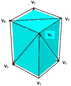
p_w_1: [1,2,4,1] & [2,3,4,2] with tetrahedron volumes equal to zero each, since the tetrahedron of zero height is formed with point P (0,0,0).
p_w_2: [2,6,3,2] & [6,7,3,6] with tetrahedron volumes equal to 2m3 each, since the normal orientation is in + direction of x axis.
p_w_3: [6,8,7,6] & [6,5,8,6] with tetrahedron volumes equal to 2m3 each, since the normal orientation is in + direction of y axis.
p_w_4: [5,1,4,5] & [5,4,8,5] with tetrahedron volumes equal to zero each, since the tetrahedron of zero height is formed with point P (0,0,0).
p_r_1: [4,3,8,4] & [3,7,8,3] with tetrahedron volumes equal to 2m3 each, since the normal orientation is in + direction of z axis.
p_g_1: [1,2,5,1] & [2,6,5,2] with tetrahedron volumes equal to zero each, since the tetrahedron of zero height is formed with point P (0,0,0).
The volume of so formed 12 tetrahedrons (by joining triangle vertices with point P) is computed using implemented determinant method.
double de.hft.stuttgart.volumecalculator.NewVoluleCalculator.det(Vertex a, Vertex b, Vertex c)
The summation (=12 m3) of tetrahedron volumes gives the volume (=lXbXh=2m X2m X3m=12 m3) of cuboid geometry.
[edit] Center Geo-coordinates of Building Geometry
The building geometry consists of building, building parts and building installation components. The vertex table of each component geometry is examined and listed vertices are compared to find out the vertices with minimum and maximum values of x, y and z coordinates. The midpoint of minimum and maximum coordinates gives the center geo-coordinates of component geometry. Then, these computed center geo-coordinates of every component are averaged to get the center of whole building geometry.
The implemented method requires the component geometry with particular level-of-detail and surface type as input parameter and returns center geo-coordinates (x, y and z values) of geometry. The average of component geometry's center geo-coordinates is calculated to get center of whole building geometry.
double[] de.hft.stuttgart.featurehandler.GeometryHandler.getCenterOfGeometry(Geometry geom)
double[] de.hft.stuttgart.linearalgebra.Compare.getAverage(double[] a, double[] b)
[edit] Sun & Wind occluded boundary surface area calculation
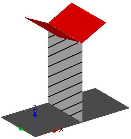
The sun and wind occlusion calculation of boundary surfaces is performed for the analysis of solar heat gain and ventilation losses through boundary surfaces. The percentage occlusion of boundary polygon areas due to adjacent boundary polygons is computed to find out exposed boundary surface areas. The occlusion calculation is demonstrated using "20140218_TwoSimpleBuildings_LOD2.xml" model. The CityGML file contains two adjacent building models with LoD2 solid geometry and boundary surfaces (Roof, Wall, Ground) as shown.
For a given building, every boundary surface polygon (called subject polygon) is checked with the adjacent coplanar boundary surface polygons (called candidate polygon) of neighboring buildings for occlusion. There are certain criterias that filter out the far distant geometries and non-coplanar & far distant candidate polygons which are less probable to occlude the given subject polygon. Then, the percentage of occlusion by the set of probable candidate polygons is calculated and added to get total occlusion of subject polygon area.
New Criteria 1: Filtering of distant geometries by Kd-tree algorithm - During the run-time of Geometric Preprocessing workflow step, it was observed that the filterByBBox() method was consuming maximum run-time and consequently found time-inefficient. So, in order to avoid this run-time bottleneck, the filterByBBox() method is replaced by the findNearestNeighbours() method which requires the subject geometry, Kd-tree of nodes and number of nearest neighbors to be searched as the arguments.
List<CityObject> findNearestNeighbours(Geometry geom, KDTree<CityObject> kdNodes, int neighboursCount)
Before calling this method implementation, a 2D tree is built based on the nodes (parent-child hierarchy) having the candidate's building center geo-coordinates as a key and the corresponding cityobject as a value. Then, this tree is queried with the center geo-coordinates of the subject and the neighbors count to retrieve the list of potential cityobject candidates occluding the subject. The measured average computation time using this new Kd-tree algorithm for a building (e.g. DEBWL0010000mztJ) in Walheim CityGML model was equal to 15 msec. against the 375 msec. using the old BBox method and which also resulted in significant reduction in overall execution time of the geometric preprocessing workflow step. For more information, please see Kd-tree implementation in Java and Kd-tree basics
Old Criteria 1: Filtering of distant geometries by BBox algorithm - For CityGML file containing hundreds of building models, the far distant building geometries (called CityObject geometries) from subject building geometry could not contribute in occlusion of subject building's boundary surface polygons. So, these geometries are omitted from further investigation with the condition that the extended (by delta distance) bounding box of subject geometry does not intersect the bounding box of CityObject geometry.
The implemented method adds the CityObject geometry to the list of filtered candidate geometries, if CityObject geometry intersects extended bounding box of subject building geometry. This filtered geometry list per subject building geometry is further inspected for coplanarity condition with the subject building's boundary surface polygons.
List<Geometry> eu.simstadt.geompreproc.SunWindExposedEngine.filterByBBox(Geometry geom, List<CityObject> cityObjects, double dist)
boolean eu.simstadt.geompreproc.SunWindExposedEngine.intersect(Geometry geom1, Geometry geom2, double delta)
Criteria 2: Filtering of NonCoplanar Candidate polygons - As shown in right figure above, the adjacent candidate polygon which is coplanar to subject polygon results in a significant overlap (Intersection result is Polygon) between them and other non-coplanar candidate polygons results in no overlap between them (Intersection result is LineString). The candidate polygons of filtered geometry which are non-coplanar to subject polygons are removed based on the angle between the surface normal of subject and candidate polygons.
The implemented method examines the value of magnitude of cross-product between the surface normals greater than the threshold value of 0.2 (angle greater than 10 degrees). If the value is greater than 0.2 then that the candidate polygon (non-coplanar polygon) is removed and appended to the list of removed polygons.
void eu.simstadt.geompreproc.SunWindExposedEngine.filterNonCoplanarPolygons(Polygon subject, HashMap<Integer, Vertex> vertices, double[] n0_subject, List<Geometry> others)
Criteria 3: Filtering of Distant Coplanar Candidate polygons – The adjacent coplanar candidate polygon contributes to overlap with the subject polygon and there is no possibility of significant overlap of distant coplanar candidate polygons with subject polygon. So, the distant coplanar candidate polygons for given subject polygons are not considered in occlusion calculation based on the distance between them.
The implemented method computes the distance between subject and candidate polygon. If the distance is greater than the threshold of 0.25, then that candidate polygon is removed and appended to the list of removed polygons.
void eu.simstadt.geompreproc.SunWindExposedEngine.filterDistantPolygons(Polygon subject, HashMap<Integer, Vertex> vertices, double[] n0_subject,
List<Geometry> others)
In final step, the adjacent coplanar candidate polygons (unremoved polygons) and subject polygon are passed to overlay function from Java Topology Suite (JTS) library which returns the geometry (Polygon, LineString, Empty GeometryCollection) of overlapped portion between the polygons.
The implemented occlusion method generates the JTS specific subject and candidate geometries for passing them as parameters to overlay function. Then, the occlusion ratio of overlapped geometry area to the subject polygon area is calculated to find out the percentage of subject polygon occlusion.
double eu.simstadt.geompreproc.SunWindExposedEngine.occlusion(Polygon subject, HashMap<Integer, Vertex> vertices, double[] n0_subject, Polygon p,
HashMap<Integer, Vertex> p_vertices, CityObject cityObject)

Geometry com.vividsolutions.jts.operation.overlay.OverlayOp.overlayOp(Geometry geom0, Geometry geom1, int opCode)
For the shaded region as shown in test example figure, the subject polygon (b1_p_w_2) of building 1 is occluded 100% with the 50% overlap each from the candidate polygons (b2_p_w_4 and b2_p_w_5), since the adjacent candidate boundary surface of building 2 is triangulated into two triangle polygons (b2_p_w_4 and b2_p_w_5).
[edit] Volume calculation (using tetgen library)
Calculates a volume of a given solid geometry (CityDoctor data structure). The algorithm works as follows:
take a solid geometry
create necessary input file for tetgen
triangulate the solid using tetgen as a seperate process (tetrahedralization)
read the output files of tetgen
sum up the volume of each tetrahedron
The algorithm will be explained by a simple example.
The building model shown above is given as a CityGML file (Volume-SimpleBldg.xml). It contains a building model with a LoD2 solid geometry and boundary surfaces (Roof, Wall, Ground). The model is parsed and mapped to the internal CityDoctor data structure. The solid geometry of the resulting building b is then passed to the volume calculation class:
VolumeCalc volumeCalc = new VolumeCalc();
double vol = volumeCalc.calcVolume(b.getId(), b.getLod2SolidGeometry());
create necessary input file for tetgen
The solid geometry will be stored as a so-called SMESH file. The name of this file is always "feature.smesh". It consists of a node list and a face list. A list of holes and attributes can be specified, but is not used in our implementation. A detailed description of the file format can be found here: http://wias-berlin.de/software/tetgen/fformats.smesh.html.
#example building as SMESH file
8 3 0 0
1 2 2 3
2 2 2 0
3 0 0 3
4 2 0 3
5 2 0 0
6 0 2 3
7 0 0 0
8 0 2 0
6 0
4 3 4 1 6
4 7 8 2 5
4 8 7 3 6
4 2 8 6 1
4 5 2 1 4
4 7 5 4 3
0
0
triangulate the solid using tetgen as a seperate process (tetrahedralization)
After the SMESH file is created, tetgen will be executed (see Class CommandExecution.java)
Runtime.getRuntime().exec(path + "\\tetgen.exe " + "-p \""+ path + "\\feature.smesh\"");
tetgen calculates a tetrahedralization of the given solid. In our example, 6 tetrahyra will be generated.
The result is stored into two files, the node list and the list of tetrahedrons.
read the output files of tetgen
node list: feature.1.NODE
tetrahydron list: feature.1.ELE
The file structure of the node list is:
	 number_of_nodes 3 0 0
	 node_id x y z
	 ...

	 node_id starts with 1.
The file structure of the tetrahedron list is:
	 file structure is
	 number_of_tet 4 0
	 tet_id v0 v1 v2 v3
	 ...

	 tet_id starts with 1.
A detailed description of the file format can be found here: http://wias-berlin.de/software/tetgen/fformats.smesh.html.
In the example, the node list file is
feature.1.NODE
8  3  0  0
   1    2  2  3
   2    2  2  0
   3    0  0  3
   4    2  0  3
   5    2  0  0
   6    0  2  3
   7    0  0  0
   8    0  2  0
and the tetrahedron list is
feature.1.ELE
6  4  0
    1       1     8     7     3
    2       3     1     8     6
    3       5     1     2     7
    4       2     1     8     7
    5       4     1     5     3
    6       1     7     5     3
sum up the volume of each tetrahedron
The volume of a tetrahydron with vertices a=(a1,a2,a3), b=(b1,b2,b3), c=(c1,c2,c3), and d=(d1,d2,d3) is given by
(1/6)*|det(a-b),(b-c),(c-d)|
In the example, the volume is 12 m3. It is correct, as the building is a box shape with dimensions 2m x 2m x 3m.
The tetrahedralization is done bythe external software program tetgen (http://wias-berlin.de/software/tetgen/). Currently version 1.4.3 is used.
[edit] Polygon calculations (previous documentation version)
Per polygon the following values are calculated. The polygon is usually connected to a boundary surface such as ground, wall or roof surface. It might be a good idea to aggregate values per boundary surface. However, this is not done yet.
[edit] normal vector
The normal vector of a polygon is calculated using the method getNormalOfSurface() of the class de.hft.stuttgart.citydoctor.util.Utils. Nazmul, which algorithm is used here to calculate the normal vector?
one approach is to calculate the right most point of the polygon and take the triangle using this point and the points before and after it. This triangle is always inside the polygon!
[edit] azimuth and tilt
to be documented
[edit] area
The algorithm to calculate the area of a planar polygon in 3D space is described here:
http://softsurfer.com/Archive/algorithm_0101/algorithm_0101.htm#2D%20Polygons
The wall surfaces have an area of 6 square meter each, the roof and the ground 4 square meter.
To compute the area of a 3D planar polygon 3 inputs are needed:
- the number of vertices in the polygon,
- an array of n+1 points in a 2D plane with V[n]=V[0],
- a normal vector of the polygon's plane
Then take the absolute value of normal and select largest coordinate to ignore for projection. Compute area of the 2D projection and Scale to get the area before projection. The whole process has been explained below.
[edit] 3D Planar Polygons (previous documentation version)
An important generalization is for planar polygons embedded in 3D space [Goldman, 1994]. We have already shown that the area of a 3D triangle ![]() is given by half the magnitude of the cross product of two edge vectors; namely,
is given by half the magnitude of the cross product of two edge vectors; namely, ![]() .
.
The Standard Formula
There is a classic standard formula for the area of a 3D polygon [Goldman, 1994] that extends the cross-product formula for a triangle. It can be derived from Stokes Theorem. However, we show here how to derive it from a 3D triangular decomposition that is geometrically more intuitive.
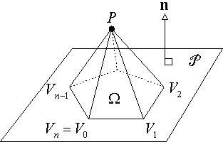 A general 3D planar polygon
 ![]() has vertices
has vertices ![]() for
for ![]() with
with ![]() , where all the vertices lie on the same 3D plane P which has a unit normal vector n. Now, as in the 2D case, let P be any 3D point (not generally on the plane P ); and for each edge
, where all the vertices lie on the same 3D plane P which has a unit normal vector n. Now, as in the 2D case, let P be any 3D point (not generally on the plane P ); and for each edge ![]() of
of ![]() , form the 3D triangle
, form the 3D triangle ![]() . We would like to relate the sum of the areas of all these triangles to the area of the polygon
. We would like to relate the sum of the areas of all these triangles to the area of the polygon ![]() in the plane P . But what we have is a pyramidal cone with P as an apex over the polygon
in the plane P . But what we have is a pyramidal cone with P as an apex over the polygon ![]() as a base. We are going to project the triangular sides of this cone onto the plane P of the base polygon, and compute signed areas of the projected triangles. Then the sum of the projected areas will equal the total area of the planar polygon.
as a base. We are going to project the triangular sides of this cone onto the plane P of the base polygon, and compute signed areas of the projected triangles. Then the sum of the projected areas will equal the total area of the planar polygon.
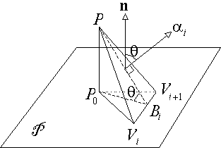 To achieve this, start by associating to each triangle
 ![]() an area vector
an area vector ![]() , which is perpendicular to
, which is perpendicular to ![]() , and whose magnitude we know is equal to that triangle's area. Next, drop a perpendicular from P to a point P0 on P , and consider the projected triangle
, and whose magnitude we know is equal to that triangle's area. Next, drop a perpendicular from P to a point P0 on P , and consider the projected triangle ![]() . Then drop a perpendicular P0B'i from P0 to B'i on the edge
. Then drop a perpendicular P0B'i from P0 to B'i on the edge ![]() . Since PP0 is also perpendicular to ei, the three points PP0B'i define a plane that is perpendicular to ei, and thus PB'i is a perpendicular from P to ei. Thus |PB'i| is the height of
. Since PP0 is also perpendicular to ei, the three points PP0B'i define a plane that is perpendicular to ei, and thus PB'i is a perpendicular from P to ei. Thus |PB'i| is the height of ![]() , and |P0B'i| is the height of Ti. Further, the angle between these two altitudes =
, and |P0B'i| is the height of Ti. Further, the angle between these two altitudes = ![]() = the angle between n and
= the angle between n and ![]() since a 90° rotation (in the PP0B'i plane) results in congruence. This gives:
since a 90° rotation (in the PP0B'i plane) results in congruence. This gives:
This signed area computation is positive if the vertices of Ti are oriented counterclockwise when we look at the plane P from the side pointed to by n. As in the 2D case, we can now add together the signed areas of all the triangles Ti to get the area of the polygon ![]() . Writing this down, we have:
. Writing this down, we have:
Finally, by selecting P = (0,0,0), we have PVi = Vi and this produces the concise formula:

which uses 6n+3 multiplications and 4n+2 additions
Similar to the 2D case, this is a signed area which is positive when the vertices are oriented counterclockwise around the polygon when viewed from the side of P pointed to by n.
[edit] Classification
== Energy analyse library ==
