CityGML usage in SimStadt
Contents |
[edit] Documentation
A description of the internal CityDoctor Java data structure for CityGML objects is Media:CityDoctor_DataStructure.pdf
[edit] Building
In CityGML, a building may consist of several building parts. Each building part usually has the same set of attributes, but different values. The distinction between Building and BuildingPart is not well specified. See the CityGML modelling guidelines for the ongoing discussion. Building Parts are not suited to model room and the like.
For simulation, I would suggest to deal with building and building part at the same level. Simulation is done on building part level. For simplicity I would suggest not to distinuish between "main building" and "building part", but define that if a Building consists of Building Parts, the Building itself has no geometry element. The Building geometry is the aggregation of the geometries of the different Building Parts. In this model a building can have either a geometry or consists of building parts.
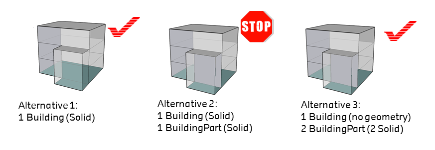
To specify the necessary attributes, the Abstract Building will be extend as both Building and BuildingPart inherit from Abstract Building.
[edit] Abstract Building
The geometry of an Abstract Building should be modeled as recommended in the SIG3D modeling guidelines. The volumetric parts of the geometry should be modeled as Solids, the non-volumetric parts as MultiSurface. In LoD2, Boundary Surfaces should be used.
[edit] Roof type
Standardised Roof type are listed in a the following .xml code list:
http://grepcode.com/file/repo1.maven.org/maven2/org.jvnet.ogc/schemas/1.0.0/citygml/codelists/RoofTypeType.xml
Each Roof type is referenced by a 4-digits code according to SIG3D standard:
| Code | Description |
|---|---|
| 1000 | flat roof |
| 1010 | monopitch roof |
| 1020 | skip pent roof |
| 1030 | gabled roof |
| .... | ... |
| 1130 | combination of roof forms |
[edit] Height
The height of a building given by a set of attributes as defined in the SIG3D modeling guidelines:
- minTerrainHeight: lowest point of terrain [in absolute coordintes] (Min Geländepunkt)
- minEavesHeightRel: lowest point of eaves [in absolute coordinates] (Min Höhe Trauflinie)
- maxEavesHeightRel: highest point of eaves [in absolute coordinates] (Max Höhe Trauflinie) (needed? Maybe not)
- maxRidgeHeightRel: highest point of roof ridge [in absolute coordinates] (Max Höhe Firstlinie)
- relative mean building height: meanBuildingHeightRel = (minEavesHeightRel + maxRidgeHeightRel)/2
The minTerrainHeight is the reference point to all relative heights.
calculation of attributes based on geometry
If these values are not measured during data capturing, they need to be calculated based on the building geometry.
The minTerrainHeight can be either calculated using the terrain model or terrain intersection curve. Otherwise, the minTerrainHeight is set to the min z-value of the building geometry. Using the terrain model is more accurate.
In LoD1, roof structure is not available, so it is more or less impossible to estimate the eaves and roof rigde height. The mean height of the building can be calculated as the difference of the lowest point of terrain and the max. z-value of the building geometry coordinates: meanBuildingHeightRel=max z-value - minTerrainHeight.
Under the assuption that no roof overlaps are modeled in Lod2, the lowest point of eaves is the min z-value of all polygons that belong to a roof surface. The highest point of roof rigde is the max z-value of all polygons that belong to a roof surface. This highest point of eaves is hard to calculate as eaves and roof ridge are not explicitly given in the data model.
The following example illustrates the calculation of the height attributes. The building geometry is given as LoD2 solid with BoundarySurfaces.
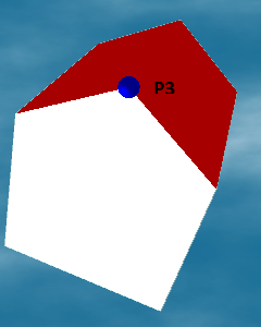
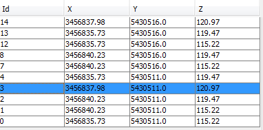
- minTerrainHeigt = 115.22, uom=m, metadata=3
- minEavesHeightRel = 4.25, uom=m, metadata=1
- maxEavesHeightRel = 0, uom=m, metadata=99
- maxRidgeHeightRel = 5.75, uom=m, metadata=1
- meanBuildingHeightRel = 5.0, uom=m, metadata=2
The same building with LoD1 solid geometry. Based on this model, at least the mean height of the building can be derived. Of course, some attributes might be measured during data caption already. Let us assume that the highest point of the building was measured and stored in the CityGML attribute measuredHeight. It is very likely that this measured hight is similar to maxRidgeHeightRel, so we use it like that.
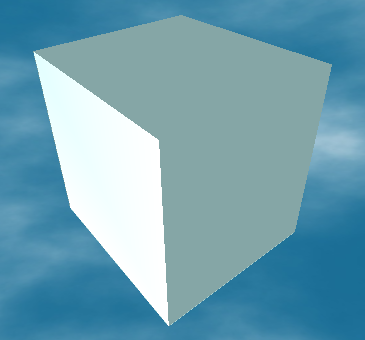
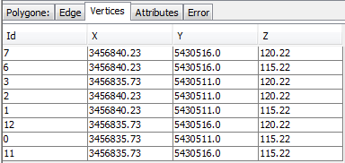
- minTerrainHeigt = 115.22, uom=m, metadata=3
- minEavesHeightRel = 0, uom=m, metadata=99
- maxEavesHeightRel = 0, uom=m, metadata=99
- maxRidgeHeightRel = 5.75, uom=m, metadata=0
- meanBuildingHeightRel = 5.0, uom=m, metadata=1
SimStadt CityGML ADE:
- <gen:measureAttribute name="minTerrainHeight"><gen:value uom="#m">Wert</gen:value></gen:measureAttribute>
- <gen:measureAttribute name="minEavesHeightRel"><gen:value uom="#m">Wert</gen:value></gen:measureAttribute>
- <gen:measureAttribute name="maxEavesHeightRel"><gen:value uom="#m">Wert</gen:value></gen:measureAttribute>
- <gen:measureAttribute name="maxRidgeHeightRel"><gen:value uom="#m">Wert</gen:value></gen:measureAttribute>
- <gen:measureAttribute name="meanBuildingHeightRel"><gen:value uom="#m">Wert</gen:value></gen:measureAttribute>
[edit] Boundary surfaces
Boundary Surfaces such as Ground-, Wall-, and RoofSurfaces add additional semantics to the building geometry. A Boundary Surface consists of a set of (non-overlapping) polygons. Very often, each Boundary Surface has one Polygon only. However, this is not always the case, so we should use a more general approach. From my point of view it would make sence to aggregrate all polygons, that are connected and have a similar normal vector to one Boundary Surface.
open issues:
- Unfortunately, in CityGML Boundary Surfaces are not available in LoD 1. As we need a place to store attributes on surfaces also in LoD 1, we need to introduce Boundary Surfaces in LoD 1 in our ADE.
- in principle, a polygon could belong to more than one Boundary Surface. How do we deal with that? One problem could be the area calculation, in this case the polygon counts for two different Boundary Surfaces.
[edit] SurfaceArea
The area of a Boundary Surface is the sum of the area of all polygons that belong to the Boundary Surface.
units of measurement (uom): m2
[edit] VisibleSurfaceArea
The area of the Boundary Surfaces that is not adjacent to other buildings.
units of measurement (uom): m2
metadata
[edit] AdjacentSurfaceArea
The area of the surface part that is adjacent to another surface. This is usually the case if two buildings share a common wall.
units of measurement (uom): m2
metadata
- calculated without terrain intersection curve
- calculated with terrain intersection curve
- tolerance value?
open issues:
- list of adjecentAbstractBuildings (is this necessary?)
- is this only needed for Wall Surfaces? I think so.
- how do we deal with parts of the surface that is under the terrain? I think we need to take terrain intersection curve into account
[edit] Orientation
- calculate normal vector of one polygon of the Boundary Surface should be sufficient
- derive inclination and azimuth if necessary
[edit] uValues
- is it sufficient to define a uValue per boundary surface?